A Trip to Jalan Pasar
Yesterday the Group members (Tong Jiun, Jin Yang, I), Evans and Yuk Jiun took a trip down to Jalan Pasar after recommendation by Dr.Jaga that we could get all of the components we need to make the IC there as it is the centre for all electrical and electronic parts. Since class ended at 12pm yesterday, we had out lunch and took a train up to Jalan Pasar and indeed there are alot of electric and electronic stores along the whole street. It's abit like Lowyat Plaza for tech gadgets. After visiting a few shops, we found the shop that sells all the components that is needed for the IC Project.
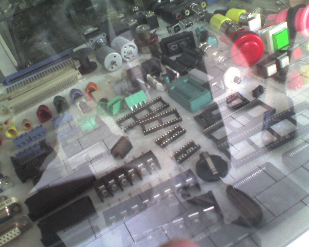
Electronic components that are sold in the shop.

That's us picking out the wires for the IC Project.
After spending some time there we got:
1x Bread Board
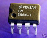
2x Amplifier IC
2x OR Gate IC
2x AND Gate IC
2x 470 ohm Resistor
2x Transistor
3x Switch
2x Battery Holder
2m Wires

Parts that we bought.

The Logic Gate ICs.
Tomorrow we would be using the EE Lab to carry out experiments on whether the IC is working with the current circuit plans. Once everything is finalized and the IC is working, I will post the Circuit Plans on the blog.
posted by Ken Seong at 6:52 AM
0 comments
![]()